Computer Vision (or CV) is a field in AI that develops techniques to help
computers to “see” and “understand” the contents of digital images like
photographs and videos, and to derive meaningful information.
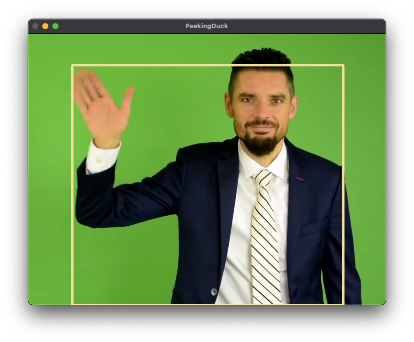
Common CV applications include object detection to detect what objects are
present in the image and pose estimation to detect the position of human limbs
relative to the body.
PeekingDuck allows you to build a CV pipeline to analyze and process images
and/or videos. This pipeline is made up of nodes: each node can perform certain
CV-related tasks.
This section presents two basic “hello world” examples to demonstrate how to use
PeekingDuck for pose estimation and object detection.
To perform pose estimation with PeekingDuck, initialize a new PeekingDuck project using
the following commands:
Terminal Session
[~user] > mkdir pose_estimation
[~user] > cd pose_estimation
[~user/pose_estimation] > peekingduck init
peekingduck init will prepare the pose_estimation folder for use with
PeekingDuck.
It creates a default pipeline file called pipeline_config.yml and a src folder
that will be covered in the later tutorials.
The pipeline_config.yml file looks like this:
If your computer has a webcam attached, you can use it by changing the first
input node (line 2) as follows:
1nodes:2-input.visual:3source:0# use webcam for live video4-model.posenet# use pose estimation model5-draw.poses# draw skeletal poses6-output.screen
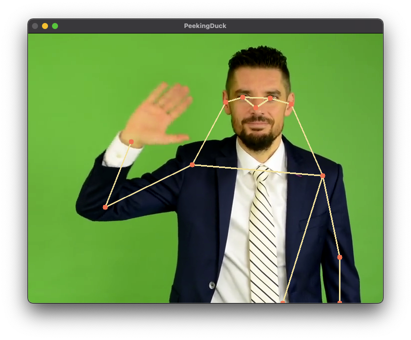
Now do a peekingduck run and you will see yourself onscreen.
Move your hands around and see PeekingDuck tracking your poses.
To exit, click to select the video window and press q.
Note
PeekingDuck assumes the webcam is defaulted to input source 0.
If your system is configured differently, you would have to specify the
input source by changing the input.visual configuration.
See changing node configuration.
PeekingDuck comes with a rich collection of nodes that you can use to create
your own CV pipelines. Each node can be customized by changing its
configurations or settings.
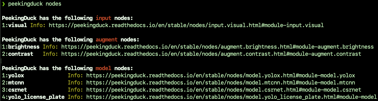
To get a quick overview of PeekingDuck’s nodes, run the following command:
Terminal Session
[~user] > peekingduck nodes
You will see a comprehensive list of all PeekingDuck’s nodes with links to their
readthedocs pages for more information.
PeekingDuck supports 6 types of nodes:
A PeekingDuck pipeline is created by stringing together a series of nodes that
perform a logical sequence of operations.
Each node has its own set of configurable settings that can be modified to
change its behavior.
An example pipeline is shown below:
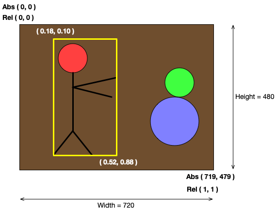
For an image of width \(W\) and height \(H\), the absolute image coordinates are
integers from \((0, 0)\) to \((W-1, H-1)\).
E.g., for a 720 x 480 image, the absolute coordinates range from
\((0, 0)\) to \((719, 479)\).
Relative bounding box coordinates
For an image of width \(W\) and height \(H\), the relative image coordinates are
real numbers from \((0.0, 0.0)\) to \((1.0, 1.0)\).
E.g., for a 720 x 480 image, the relative coordinates range from
\((0.0, 0.0)\) to \((1.0, 1.0)\).
This means that in order to draw a bounding box onto an image, the bounding box
relative coordinates would have to be converted to the image absolute coordinates.
Using the above figure as an illustration, the bounding box coordinates are
given as \((0.18, 0.10)\) top-left and \((0.52, 0.88)\) bottom-right.
To convert them to image coordinates, multiply the x-coordinates by the image
width and the y-coordinates by the image height, and round the results into
integers.